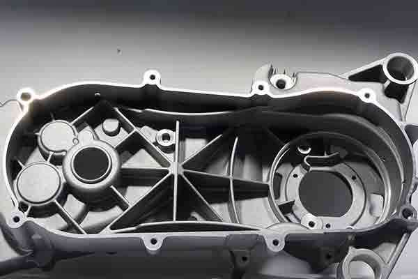
Pressure die casting is the fastest and most cost-effective way to make high volumes of parts in aluminum, zinc or magnesium. Die cast parts have excellent surface finishes, maintain consistent features and tolerances, and waste little raw material.
Pressure die casting is used to make engine blocks and motor housings, appliance parts, heat sinks, fittings, brackets and myriad other common industrial and commercial products.
If you are developing a product and considering pressure die casting for a project, you should be aware that all cast parts must contend with the issue of porosity. It is unavoidable but it is controllable. To mitigate the effects of porosity in your parts, let’s look at what causes it and how to use best design practices to manage porosity for superior results.
What is porosity?
Porosity refers to a hole or void in an otherwise solid cast metal part. Pores can range in size from microscopic (micropores) to larger voids measurable in cubic millimeters or larger. Pores are not always circular in cross-section but can also take the form of irregular linear cracks.
Porosity has two main causes: solidification shrinkage and gas porosity. Let’s look more closely at the root causes for these two types and then we’ll propose strategies to deal with them.
Solidification Shrinkage
After molten metal is injected into a mold cavity it begins to solidify when it contacts the relatively cooler walls of the tool. This solidification causes the metal to shrink, but the rate at which this happens will vary depending on the geometry of the mold tool and the type of alloy being used.
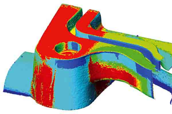
Modeling software is used to predict where pores are most likely to develop. Image courtesy of Flow3D.
The semi-liquified portion of metal further away from the tool wall is called slush, and it’s this area where pores are more likely to form. In addition, as the molten metal becomes a solid it may block the passage of liquid to other places in the mold. This can create pores by preventing full liquification of all features of the design.
Gas Porosity
Gas pockets form in a few ways. In the case of aluminum, hydrogen may fall out of suspension and fill voids with hydrogen gas.
There also may be air trapped within the mold tool that was not fully evacuated or vented as the cavity filled. This trapped air is called entrained.
Finally, other liquids may get mixed with the molten metal during injection. These might be mold release agents, leaked hydraulic fluid or even atmospheric humidity. Any of these can rapidly vaporize and form gas bubbles. Liquids or oils that don’t evaporate become contaminants that may form inclusions in the final part.
Three Types of Porosity
We’ve just looked at the two major causes of pores: solidification shrinkage and gas porosity. In both cases, pores may be produced that form one of three major sub-categories.
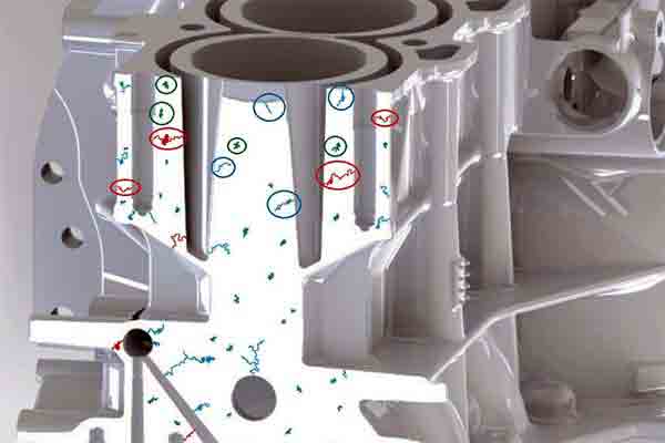
Illustration of blind, through and enclosed pores. Image courtesy of Godfreywing.
1. Blind Porosity
The pore starts at the surface of a feature and ends somewhere within the body of the metal. These types don’t usually affect mechanical strength but they may invite corrosion.
It’s possible to seal these pores after casting, especially if the part needs to hold pressure such as in a hydraulic cylinder.
2. Through Porosity
The pore starts at the surface and creates a channel all the way through the feature and out the opposite wall. This causes a leak and would need to be sealed from both sides.
3. Fully Enclosed Porosity
These pores exist within the body of the metal and are not exposed to the outside unless they are later penetrated during post-machining. The existence of such pores is normally not apparent unless the part is subject to a computed tomography (CT) scan after casting or if the part is cut open for diagnostic reasons.
Allowable Tolerances for Porosity
Porosity typically accounts for an average of 5% of the total volume of the part. It is not realistic to eliminate porosity but rather to ensure that it’s contained in those areas where it’s not detrimental to part function or appearance.
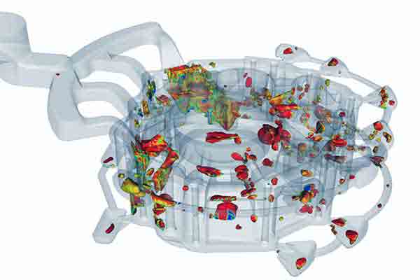
Simulation of micropores in a PDC part. Image courtesy of Flow3D.
Therefore when a design drawing or CAD file is produced, these areas should be clearly designated with a set of specifications and tolerances for allowable defects, just as would be the case with dimensional tolerances. Specifications for porosity usually take the form of: number of pores within a given volume; maximum permitted size per pore; and total volume percentage per part.
Manufacturers will then use this information to fine-tune the molding parameters accordingly. This will mean allowing for porosity in some less critical areas while preventing it in others. There will always be these trade-offs to consider so it’s best to take them into account at the beginning of a project.
Diagnostic Tools for Porosity Analysis
Modeling software now exists to help product designers and manufacturers to predict where porosity is most likely to occur. These models are based on sophisticated analysis of many molding parameters such as fill, mold profile, wall thickness, dwell times, temperatures, alloy composition and many others.
Using this information, product engineers can improve their mold designs accordingly, while molders can also optimize their set-ups in advance rather than rely on costly and time-consuming trial and error.
Tool Design Tips for Porosity Prevention
There are some tool design best practices that should be employed to help prevent the most common causes of porosity.
Wall Thickness
Problem
By far the most common cause of porosity is unequal cooling of the part inside the cavity, which is in turn a function of varying wall thicknesses.
Solution
The easiest and most expedient way to prevent this is to maintain consistent wall thicknesses whenever possible. That is the job of the mold tool designer. Many other important considerations, such as the design of bosses, ribs, gussets and other features, are similar to those of plastic injection molding.
Shrink Rate
Problem
The shrink rate is affected by the melting temperature of the alloy, the cooling time and the cooling temp. In the case of aluminum, which is by far the most common die casting material, the addition of silicon can lower shrink rates considerably but only within a certain alloy percentage. Too much silicon can adversely affect the mechanical performance of the alloy.
Solution
It’s best that the product developer works closely with the pressure die caster to discuss options for raw materials based on the application and design.
Entraining
Problem
It is challenging to completely remove entrained air from a mold tool, especially for complex shapes that have many internal features where air can be trapped.
Solution
There are a few strategies for mitigating entrained air. One is to improve the mold tool design so that there are no sharp corners or pockets where air cannot escape. Also, more vents can be added or the design of the gate/runner system optimized to allow escape routes for air.
Changing injection speed and pressure may help with venting but can adversely affect the part in other ways so this must be done carefully.
Final Tip
Finally, casting can be done in an environment filled with argon or some other inert gas. In this case it is best to discuss this process with the manufacturer early in the design stage.
Once the casting is done it is then necessary to find a way to accurately measure porosity in the finished part.
Technology for Measuring Porosity
New techniques have been developed to help manufacturers identify and measure porosity in a way that’s very difficult using conventional methods such as visual inspection, pressure testing or destructive testing. One of the most promising is computed tomography, or CT.
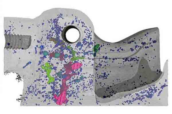
Notice that the areas nearest to the tool wall are pore-free. CT scan from Exact Metrology.
In this process, multiple high-powered X-ray photos are taken of the part and then combined to create a 3D map of the inside of the piece. This can be used for real-time process control as well as for creating computer simulations which can aid in optimizing mold tool designs. CT is becoming robust and reliable enough to qualify as a true metrology-grade measurement instrument and not just a diagnostic tool.
How does machining affect porosity?
The skin of a die cast part is the most thermally stable area. It’s the first part to solidify and shows little or no porosity within the first .5mm or more. Because pores occur in the deeper sections of castings, machining processes like tapped and threaded holes may open enclosed pores. Some castings must be able to hold air or liquid pressure, such as for hydraulic cylinders or manifolds, so these pores need to be sealed after machining.
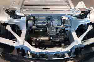
Vacuum sealed aluminum car frame. Image courtesy of Tesla.
Sealing Pores with Vacuum Impregnation
It’s common in industry to apply vacuum impregnation to the surface of die castings to effectively seal them. This is generally a three-step process:
- The part is placed in a chamber and vacuum is used to remove any trapped air in micropores.
- A sealant such as a liquid polymer resin is then put into the chamber and forced into the micropores with positive air pressure.
- Once impregnated, the part is removed from the chamber and the sealant fully cured. This is considered a one-time, permanent surface treatment.
Is Pressure Die Casting the Solution for You?
At Star, our team work with customers to ensure desigs are optimised to avoid the risk of porosity. If you’d like to work with us on your next project we can give you a free project review and work with you to get beautiful die casted parts that match your exact specifiction.
Contact us today to start your next pressure die casted project. Alternatively, choose from our range of in-house manufacturing and prototyping services.
Chris Williams is the Content Editor at Michigan CNC Machining Parts, Inc.. He is passionate about writing and about developments in science, manufacturing and related technologies. He is also a certified English grammar snob.

