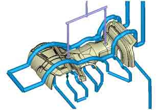
Plastic injection molding is the most widely used mass-production process in modern manufacturing. It’s so popular because useful products of every conceivable size, shape and function can be made quickly and efficiently with reliable and repeatable performance.
As versatile as it is, getting the best results from plastic injection molding still requires adhering to good tool and product design practices that must respect some of the inherent limitations and challenges of this process. To help you to improve your parts and your mold tool designs, we want to explore the causes of the four most common defects and what you can do to mitigate or eliminate them when preparing your next project.
Weld Lines
What are they?
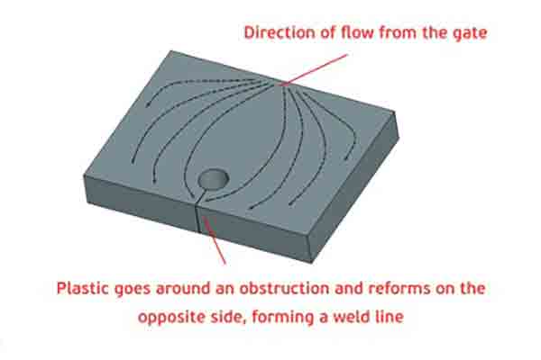
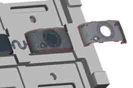
A weld line is a linear mark that looks like a scratch on the surface of a molded part, and can be found radiating away from a hollow feature or hole. A weld line is usually just a cosmetic defect but sometimes it can also weaken the part.
What causes them?
Weld lines are created when a stream of hot liquid plastic resin inside the mold cavity is forced to go around some internal obstruction and then reunite on the opposite side. The point where the two fronts reform creates a characteristic line caused by the different cooling rates of the resin fronts.
Can weld lines be prevented?
Weld lines can be mitigated by a number of tactics that depend on your part design.
- Reposition gates and runners so that resin flows around the obstruction from a different direction
- Adjust resin and cooling temperatures
- Add more cooling circuits
- Use dark colors and a matte surface finish to hide the weld line
- Painting after molding can also disguise the presence of a weld line
Gate Witness Marks
What are they?
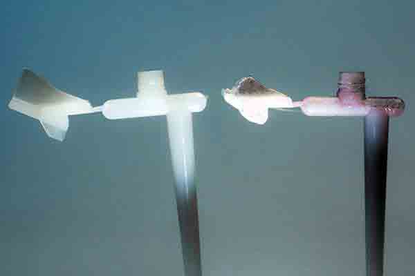
Witness marks are dimples, burrs, raised ridges or other surface texture imperfections that may be found at one or more places on a molded part.
What causes them?
A witness mark is the place where the waste sprue is broken free from the finished part. Hence, the design of the runner system determines where the mark will be located.
Can gate witness marks be eliminated?
Witness marks are a function of the molding process and cannot be completely eliminated. Their effect on the look and performance of the part can be controlled by using good design practices, including the following:
- Disguise the location of the witness within some other feature of the part
- Use a submarine gate to relocate the witness location to an unobtrusive area
- Use a fan gate to distribute the resin over a wider area with less pressure
- Use multiple, smaller runners to distribute resin and pressure
- Place the witness in an area that can be easily accessed for post-machining or sanding
Please note that all of these approaches may compromise other areas of the part design, so we advise consulting with the molder well in advance.
Parting Lines
What are they?
A parting line is a thin seam or lip, usually raised rather than recessed. Parting lines typically go around the full circumference of a molded part, unless the circumference is impeded by the location of a slider or other insert.
What causes them?
Parting lines indicate the region where the two mold halves were pressed together to form the mold cavity. When the mold opens and the solid part is removed, this junction between the mold halves produces a characteristic mark which it may be difficult to completely prevent.
Can parting lines be controlled?
There are a few strategies to mitigate the look of a parting line on your parts:
- Camouflage the line by incorporating it with other parallel or linear features
- Locate the parting line under a protruding feature like a rim or cap
- Lines can be disguised with rough surface textures and matte finishes
- Lines can be sanded smooth and repainted
Sink Marks
What are they?
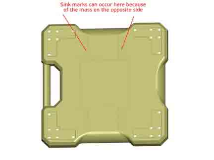
A sink mark is an unwanted depression or dip in the surface of a plastic injection molded part. They can be singular or appear as wavy, undulating lines.
What causes sink marks?
Some areas of a design – especially structural reinforcements like ribs, bosses and posts – have more thermal mass than the surrounding area. When this greater mass of liquid resin contacts the tool wall it cools down and shrinks faster than the surrounding area, creating a depression.
Because of this, balancing out thermal forces within an injected part is one of the primary challenges for the product designer as well as the tooling engineer.
Is there a way to prevent them?
There are some best practices that can help to reduce the effect of sink marks.
- Use these guidelines when designing ribs, bosses and gussets
- Maintain consistent wall thickness wherever possible, especially adjacent walls or other features
- Tooling engineers can build more cooling channels in critical areas
- Process engineers can balance injection pressure, temperature and cooling times to reduce sink marks
- Sink marks can be somewhat disguised with darker colors, matte finish and rough surface textures
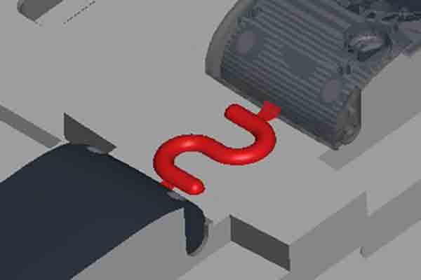
Short Shots
What are they?
A short shot is when a mold isn’t filled before gate shut-off, resulting in a part that is not fully formed.
What causes them?
Short shots can be caused by insufficient pressure, poor melt or poor part design.
During molding, the hot liquid resin naturally follows the path of least resistance, so it fills larger cavities first. Thin-walled sections are areas with more resistance to liquid flow and thus are filled last. Since the resin is cooling by this stage, these areas may solidify prematurely. Thin areas may also trap unvented gas.
Is there a way to prevent them?
Short shots are best prevented in the design stage. Here are some good practices:
- Locate gates closer to thin areas so they will be filled first
- Add vents to let gas escape
- Align thin areas parallel to the flow from the gate
- Increase wall thickness if possible
- Redesign runner systems
Want to learn more?
It is always best practice to work closely with your manufacturing partner when preparing a new project for plastic injection molding. They can offer expert advice tailored to your specific requirements. This is what you will receive at Michigan CNC Machining Parts, Inc. when you upload your CAD files for a free quotation and design review.
Chris Williams is the Content Editor at Michigan CNC Machining Parts, Inc.. He is passionate about writing and about developments in science, manufacturing and related technologies. He is also a certified English grammar snob.