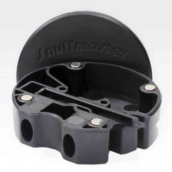
Prototype Snuff Holder and Dispenser Made with Plastic Injection Molding
Services: CNC Machining, Plastic Injection Molding, EDM, Assembly
Tooling Material: P20 tool steel
Tooling Lead Time: 20 days
Injection Material: ABS plastic
Production Lead Time: 25 days
Quantity: 1000 sets
About The Product
The Snuffmaster Lite is a snuff machine, snuff box and snuff dispenser in one single, practical and stylish device. By pressing a button, the Snuffmaster Lite loads a single dosage into the dispensing chamber, which is taken from the supply reservoir. It allows for snuffing directly from the unit, or alternately placing a dose on the back of the hand in the traditional manner.
About The Customer
Snuffmaster, which was established in 2007, is located in the Black Forest area of Germany. Company owner Alexander Gerspach created a new product which was not available on the market – a dosage machine for nasal tobacco (snuff). The benefit of this product is that it includes three different functions in one – snuff machine, dispenser and reservoir.
About The Project
This project began with the original prototype design that Star made from anodized aluminium. The client was delighted with the results of that project, but they wanted to try a new version that would save money on tooling and fabrication costs and deliver a more economical final product to the end user. After consultation with the client, we recommended plastic injection molding so we could make the Snuffmaster Lite from ABS plastic. ABS is a strong and durable plastic that’s able to handle years of daily use, and we would apply a surface texture to the finished parts that would help to simulate the look and feel of anodized aluminum.
The Snuffmaster assembly is made from three components: the case, the cover and the dispenser unit. In addition to those three pieces, there are four magnetic pins that hold the cover securely in place. After our engineers studied all the drawings, we were able to create a multiple cavity plastic injection mold tool that would mold all three components at the same time, further saving time and money.
Step 1: Mold Tooling Design
Although the three cavities were of different sizes and volumes, our tooling engineers carefully designed gates, runners and mold cooling channels to ensure that the parts formed and cooled at an equal rate to avoid warpage.
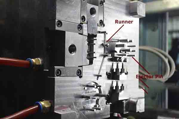
The “runner”, in red, is the path the liquid plastic follows to fill the mold. The plastic enters the empty cavity through an orifice called the “gate”. The location of the gate will leave a telltale mark on the part, called a gate witness mark.
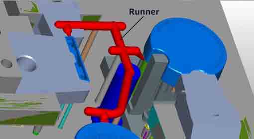
Although unavoidable in injection molding, the location of the witness mark can be optimized to avoid impacting the cosmetic appearance of the part.
Step 2: Mold Making
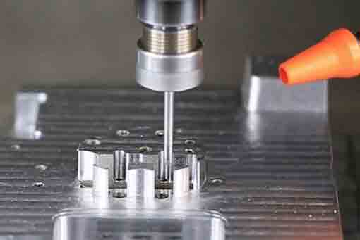
A. We recommended using P20 tool steel for the cavity and core. P20 is a semi-hardened tool steel that’s easy to machine while still being tough enough to withstand the abrasive effects of engineering plastics like ABS.
Here an end mill is used on a multi-axis CNC machine to make the profile of the case in the mold core.
The shape is the same as the original Snuffmaster but slightly undersized to account for the eventual thermal expansion of the plastic after molding.
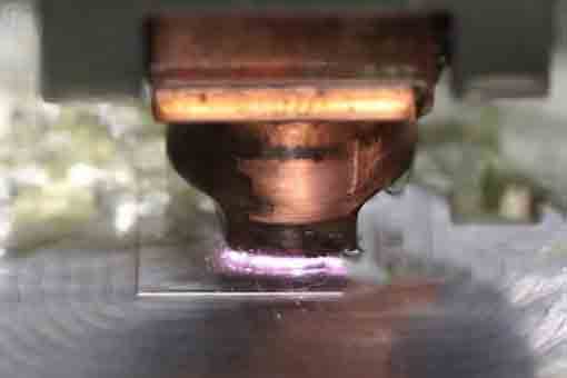
B. Electrical Discharge Machining (EDM) is a common process for making some features of a mold. A conducting electrode is made from a copper alloy and then machined to a close tolerance. It will be used to make deep holes and other features in the cavity side of the mold.
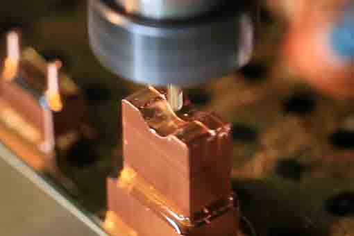
C. The electrode is placed close to the surface of the metal, bathed in a dielectric fluid. When enough charge builds up in the electrode, a spark is discharged that vaporizes the adjacent metal. The electrode is considered to be sacrificial – that is, it slowly wears away as it’s used, and must be re-made for large molds. This technique works on hardened tool steels that would be difficult to machine conventionally.
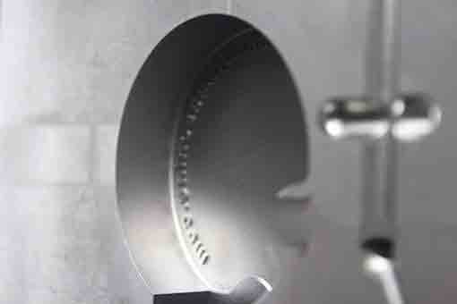
D. One of the special requirements of this project was to apply a surface texture to the finished part, which must be etched into the cavity.
This texture will later be transferred to the plastic part, helping to simulate anodized aluminum.
Our tooling engineers determined that the surface finish should correspond to the industry standard of Mold-Tech #11020.
The Mold-Tech process is a proprietary technique involving chemical etching of the tool steel under controlled conditions to make pre-determined patterns.
Step 3: Testing And Modification
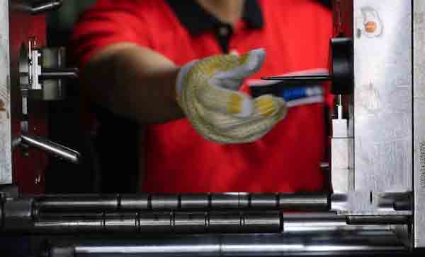
Several test runs were performed to confirm the fit and finish.
Our molding engineers realized that the ejector pins were not in the ideal location, since they still left witness marks on the part as the soft, hot plastic was pushed free of the cavity.
These pins were strategically relocated so that they performed their function without damaging the part or leaving a visible mark on the surface. This took a little trial and error before we got it just right.
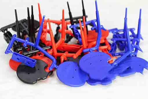
The solidified runners formed a plastic “tree”, from which the finished part needed to be removed. All remaining plastic was trimmed or sanded flush.
Step 4: Finishing
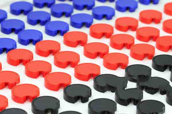
It’s not possible to perfectly match the look of anodized aluminum on ABS plastic. The choice of colors is a good approximation and helps to keep costs down.
Every job presents unique challenges which require minor adjustments to get great results. If you’d like to see how we can work with you to get such results on your next project, contact us for a free quotation today.
Anodized aluminum on ABS plastic

