The Cause And Avoidance Of Sink Marks On Plastic Injection Molded Parts
Sink marks may occur where there is a thicker section of plastic compared to the general wall thickness. The greater the difference in thicknesses, the more that shrinkage is a concern. This shrinkage can pull the component wall away from the mold surface, creating an indentation or sink mark on the opposite side of the finished part. Changing injection molding parameters or component geometry can in some cases reduce sinking to an acceptable level as follows:

1) Packing Pressure
The pressure of molten plastic going into the mold can have a great effect on thermal and mechanical stresses. Altering this pressure can be advantageous but must also be carefully controlled.
A) Sometimes sink marks can be reduced by increasing the packing pressure along with the holding time and slowing the injection speed. This will depend on the location of the gates relative to the thicker wall sections and whether there is sufficient time to fill all areas of the cavity before the gate freezes off. Although the above steps may be effective against sink marks they can also induce molded-in stress so a precise balance of forces must be maintained. And even the largest possible gate may not be able to eliminate all sink marks while a too-slow injection speed could create flow marks.
B) Sink marks are caused by unequal cooling induced from the walls of the mold tools. Altering the coolant temperature from core to cavity side may pull the sink mark in one direction or another but might cause other problems such as distortion.
C) Sink marks can sometimes be avoided by the addition of up to 0.5% of a blowing agent. However, this may lower the mechanical strength of the component slightly. So employing an agent will depend on the end use and design of the product.
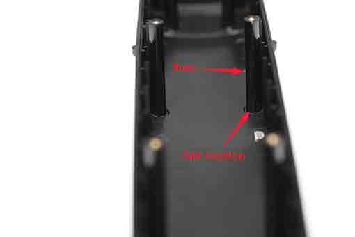
2) Ribs And Bosses
The most common locations of sink marks are in the areas surrounding ribs and/or bosses, e.g., in places where a self-tapping screw will be used for assembly. Industry guidelines have been developed to avoid such sink marks by adhering to certain design standards.
The following diagrams give examples that are used by experienced designers globally.
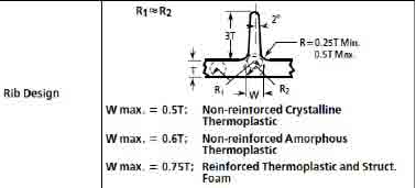
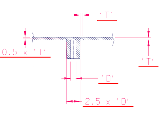
A) Proportioning the Thickness of the Base of the Rib to the Wall Thickness
Note that in the below diagram, the nominal wall thickness “T” will shrink more than the section “.5T”, the thickness of the rib at its base. Increasing the height of the rib relative to the wall thickness will tend to increase the amount of distortion and should be avoided. A rib height of “3T” should be the maximum used, as there is little mechanical advantage to be gained beyond this.
Plastic will always tend to flow along the path of least resistance. Therefore, the area of the nominal wall thickness at “T” will fill up first as the plastic is injected. Only after this section is full and the cavity pressure rises will the plastic then start to fill the rib section. This can create a surface blemish since some of the plastic has had a chance to cool while it was filling the wall section. This cooler plastic may push against the cavity side and create some cosmetic blemishes, especially on textured surfaces.
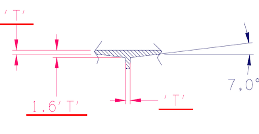
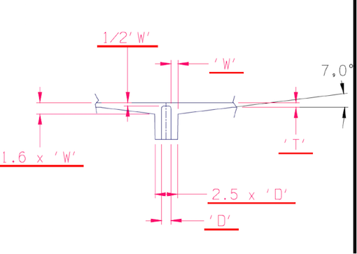
B) The Seven Degree Rule
Incorporating a gradual 7° slope at the base of a rib is useful provided that the gate is close enough to pack out this area easily to minimize distortion. The gradual rise helps to avoid surface blemishes as described in the section above. Where gas assisted injection molding is used, this geometry is convenient for the gas flow through the thicker section caused by the 7° layout.
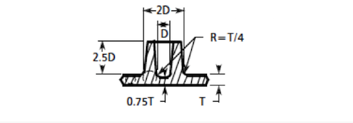
C) Boss Proportions
In bosses where the hoop strength will be lightly stressed, the standard practice is to design an o.d. which is double the i.d. For heavier loads where, for example, a self-tapping screw might be torqued down, it is advised to use an o.d. that is 2.5x the i.d. In this case, avoidance of sink marks requires special consideration.
D) Thinning of the Wall Thickness Around the Boss
This geometry seems to be quite popular with present-day designers. It must be stated that Star Rapid does not agree with its use.
It weakens the construction, thus requiring strong support ribs and also interrupts the flow during injection which might cause a surface defect especially on a textured surface.
E) The Seven Degree Rule Applied to a Boss
In this example the construction is strong while minimizing the surface blemishes caused by an interrupted flow of plastic. If there are still some blemishes, they may be removed by either decreasing the depth of the core pin and/or increasing the pin’s radii.
The gating position must also be carefully considered to ensure that the increase in wall thickness due to the 7° base is well packed-out.
In addition, the maximum radii where the face of the 7° slope meets the bottom of the boss should be no more than 0.5mm.
F) Separate Bosses from Side Walls
Whenever possible it is preferable to separate bosses from side walls rather than building up a thick section where boss and side wall are merged. This can be done by separating the boss from the wall with a supporting rib or, if necessary, by coring the wall section.
If it is impossible to relocate the boss section, then a blowing agent must be considered. Higher ratios than 0.5% may then necessitate post-processing such as painting to hide any resulting defects.
The above considerations demonstrate how important it is to carefully design mold tools and part geometries to accommodate the facts of thermal stresses within plastic injected parts. Our engineers perform a design for manufacturing review on all plastic injection molding projects to ensure that the risk of sink marks are eliminated. If you’d like to discuss your next project with one of our experts, send us your CAD file for a free quote and design review.