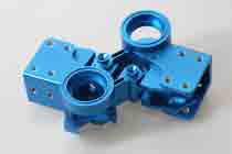
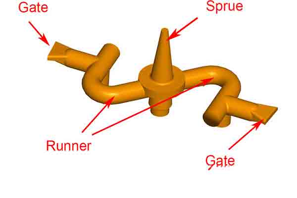
The runner and gate system used in plastic injection molding is responsible for directing molten plastic from the nozzle of the molding machine into the cavity of the tool. The gate architecture and its location affects cycle times, tooling costs, lead times, the location of witness marks and many other potential defects that are commonplace for injection molded parts.
Here’s what every product developer should know about the basics of injection mold gate design. Having this information will help you to make informed decisions when you’re consulting with your supplier to make injection mold tools.

Michigan CNC Machining Parts, Inc. technician checks a plastic injection mold tool before installation.
1. The Importance of Gate Location
The location of an injection mold gate directly affects the quality of the finished part so consider these general rules:
- The gate should be placed away from pins, cores and other internal obstructions. Otherwise this may cause weld marks as molten plastic flows around them and reforms on the other side
- Gates should be placed closest to thick walled areas to ensure complete packing
- Improper gate location can cause part distortion if the build volume of the entire part is filled unevenly
- Gates are areas of high stress. Try to locate gates away from locations on the finished part that will be affected by stress marks or the potential degrading of plastic that happens in these areas
- Gates need to be located in areas that will be easy to degate, either manually or automatically. Note that some plastics are susceptible to high sheer forces and therefore can only be degated manually
- Thin walled parts might need flow channels or additional gates to provide a sufficient volume of plastic in a minimum cycle time
2. Gate Design Can Affect Part Quality
All gates force molten plastic under pressure into the cavity which accelerates and heats the plastic as it does so. This creates a variety of effects which may need a change to gate design strategy. The most common defects include:
Jetting
If the gate is too small the resulting pressure drop through the gate will cause jetting, that is, spraying into the cavity rather than flowing smoothly. Jetting causes wavy distortions called “worming”. This may require a decrease in pressure, an enlargement of the gate or both.
Overheating
High injection speed through the gate creates heat through friction. Too much heat at this point may cause the resin to decay by destroying molecular bonds.
However, slowing down the injection speed to avoid degradation may cause other defects such as poor mechanical strength at weak weld lines. And slower cycle times means fewer parts per hour, increasing processing costs.
It’s possible therefore to divide a given volume of resin over a number of separate gate openings. This helps to dissipate pressure and avoid overheating, but it also creates multiple flow fronts which may cause weld lines and gas traps where these fronts meet inside the cavity.
3. The Difference Between Hot and Cold Runner Systems
Hot Runner
A hot gate/runner system uses an electrically heated cylinder to deliver pre-heated plastic into the mold cavity. The runner is built into the mold in the form of a manifold plate and a number of hot runner drops.
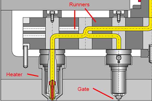
Typical hot runner system for a plastic injection mold tool
Advantages:
- Precise temperature control for better finished appearance
- Eliminates wastage in multi-cavity tools
- Decreases cycle times
Disadvantages:
- More complex and expensive
Cold Runners
Cold runner systems are less expensive, but the length of the runner represents plastic that will be wasted at each cycle, which in turn increases costs. Moving a witness mark to a more advantageous location should be balanced against the increased consumption of material due to longer runners.
4. The Pros and Cons of the Most Common Gate Types
There are different sizes and gate designs to consider, and each type has their advantages and disadvantages. Here are the most common ones:
Edge Gates
Edge gates are used most often. They are machined into the mold at the parting line and fill the cavity from the side of the part.
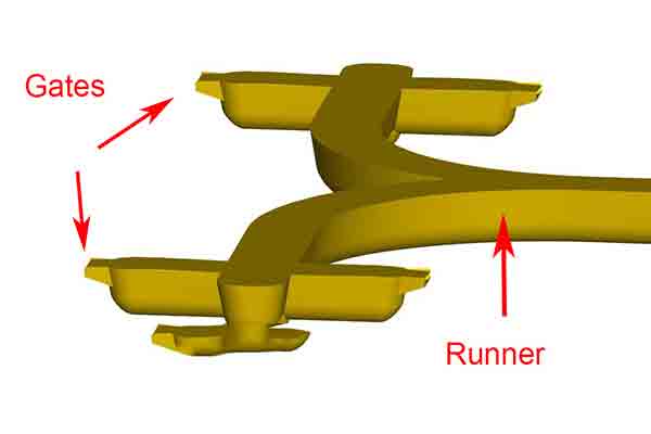
Edge gates are common for flat, thin parts
Advantages:
- Inexpensive to design and manufacture
- Easy to enlarge if necessary without removing the mold from the machine
Disadvantages:
- Location of the witness mark may not be ideal
- Plastic flowing from a single gate will create noticeable weld lines as it flows around obstructions in the mold
- High injection pressures and velocity at the small gate opening can cause the plastic to degrade
Direct or Sprue Gate
A gate built into the sprue directly where it enters the fixed or A-side of the tool.
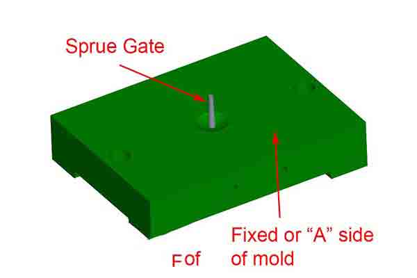
Sprue gates are built into the fixed half of injection mold tools.
Advantages:
- Easiest type of gate to make
- Able to inject large volumes of plastic quickly
- Ideal for round or cylindrical parts where concentricity is important
Disadvantages:
- Leaves behind a large witness mark with the potential for a sink mark on the opposite side
- Must be degated manually
Submarine Gate
For a submarine gate design, the runner directs plastic to the edge of the cavity at the parting line, but then the gate drops below the parting line and tunnels upward to fill the part from below. This design is only possible on two-plate mold construction.
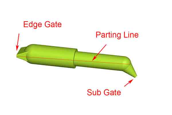
Submarine gates fill the cavity from beneath the parting line.
Advantages:
- Moves the witness mark to a more desirable location
- Excess vent gasses can be pushed up and out of the mold from below
- Degates automatically as the mold opens
Disadvantages:
- More complex, expensive and time-consuming to manufacture
Fan Gate
An alternative type of edge gate, the fan maintains a consistent thickness but spreads out to increase the volume over a larger area. Recommended for polycarbonate plastics.
Fan gates help to eliminate injection stress.
Advantages:
- Good for increasing the flow volume for thin-edged parts
- Reduces injection pressure for a given volume
Disadvantages:
- May leave a large, tab-like witness mark that must be post-processed
Are You Ready To Start Your Next Project?
The above is just a summary of a few considerations for designing gates for plastic injection molding. If you’re ready to start your next tool making project, upload your 3D CAD design for a free quote and our team of engineers and technicians can provide you with a design for manufacturing review before we start making your mold tool.
Chris Williams is the Content Editor at Michigan CNC Machining Parts, Inc.. He is passionate about writing and about developments in science, manufacturing and related technologies. He is also a certified English grammar snob.


