Plastic Injection Molding Case Study
Manufacturing Services:
plastic injection molding, CNC milling, EDM sink machining
Part Material:
Ultrason P 3010
Tool Material:
NAK80
About the Customer
Nedap Livestock Management is the global leader in farming automation using individual animal identification. They help livestock farmers to be the best performing farmers in the world.
In Michigan CNC Machining Parts, Inc. we found the right partner for the production of this part. Michigan CNC Machining Parts, Inc. supported Nedap in the feasibility study of the designed product, the production of the prototype as well as the tools. Nedap experienced this process as a real collaboration. The proactive working method and in-depth technical expertise of Michigan CNC Machining Parts, Inc. helped us make a prototype that meets the excellent quality requirements that Nedap sets for all its products. Michigan CNC Machining Parts, Inc. continuously thought along in the process, gave us fast delivery times and complied with all agreements.
About the Project
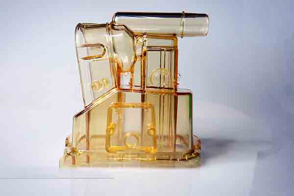
Nedap Livestock Management approached Michigan CNC Machining Parts, Inc. to help them develop one part of an innovative solution for herd management. This prototype required us to develop a complex one-piece molding as a component for a larger assembly.
Let’s take a look at how we worked closely together to turn their CAD design into a plastic injection mold tool and then a finished part that exceeded their expectations. In this case study you will find many Design for Manufacturing tips we believe can help you to bring your own product ideas to market faster and with great results.
Material Analysis
We began by reviewing the raw material. The customer specified Ultrason P 3010, a transparent resin that’s resistant to cracking and able to withstand steam sterilization. This makes it potentially suitable for valves, pipe fittings or kitchen appliances.
Every resin has unique mechanical and chemical properties that determine the best way it should be dried, melted, injected and packed. Knowing this in advance helped our engineers to design process parameters and plan for necessary draft angles.
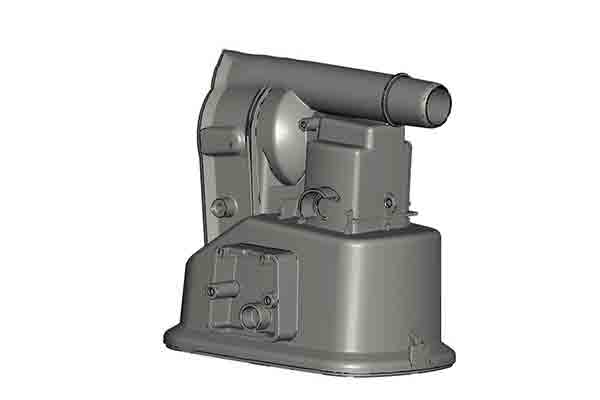
CAD file 3D image
Every resin manufacturer provides important product information
Design for Manufacturing Review
Our Design for Manufacturing review identified areas of the CAD model that could cause molding defects, so that’s always our first priority to address. We also find that at this level of detail we can offer the customer opportunities to make minor improvements that they may have overlooked, so now is a great time to implement them.
We worked with the customer to understand critical tolerances or other dimensions that could not be modified and then worked within those constraints. We then prepared a powerpoint file to share with the client, highlighting the most important areas for their feedback.
Draft Angles
Draft angles give necessary clearance between the tool wall and the adjacent part feature. More draft is better for easier mold release but there are limits so this needed to be discussed with the client.
We used sophisticated Moldflow software to analyze the CAD file and determine possible concerns. In this case, the areas indicated in red and yellow have little or no draft angle. The only way to create these part features was to design separate inserts that would withdraw from the respective faces at right angles. Other areas, indicated in blue, had sufficient draft to allow for part release in the line of draw, or direction of tool opening.
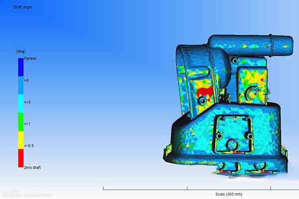
Draft angle analysis
Surface Finish
Surface finishes are first applied to the walls of the plastic injection molding tool, and are later transferred to the part. Finishes are made in many ways, including cutting, grinding, EDM, chemical etching, sanding and polishing. The customer specified two finishes, represented as SPI-A2 and MT-11000.
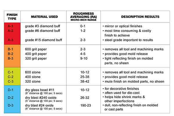
SPI chart courtesy of Alliance Laser Sales
SPI is an industry-standard reference. In this system, surface textures are categorized according to their flatness and the degree of polish using various abrasives. A2 represents a glossy, smooth surface. In order to achieve that on the plastic part, the mold cavity was successively improved from initial CNC machining and then through increasingly fine levels of sanding and polishing.
MT-11000 is a Mold-Tech classification. Mold-Tech is a proprietary photo-etch process that uses a chemical treatment to create textures and patterns on mold tools. In this case the pattern is not highly figured but achieves a soft matte, gauzy finish in this area. This is a good place to put the production date stamp.
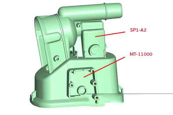
Surface finish details
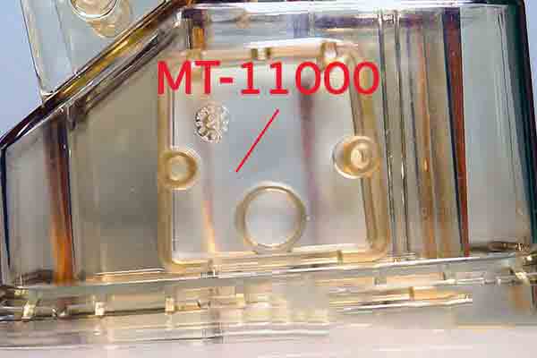
Photo-etched surface finish from MoldTech
Wall Thickness
It’s always a concern in plastic injection molding to use good design practices for wall thicknesses and related features. This is because the molten resin distributes heat throughout the entire molded part, but areas that have an unequal distribution of heat will cool at different rates. This is one of the main causes of sink marks and other potential defects.
To locate potential sink marks we did a wall thickness analysis with Moldflow. It calculated those areas most likely to create sink due to unequal mass distribution. The areas marked in yellow show where a sink mark is likely to be, because there is an extra structure on the inside of the part that adds mass. In this case it’s unavoidable without a major re-design so the customer chose to accept the results.
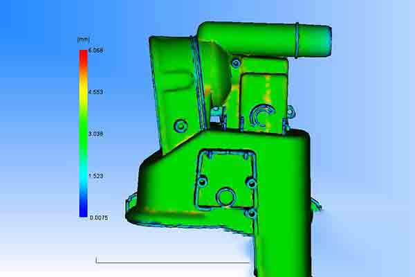
Moldflow wall thickness analysis
Line of Draw and Parting Line
The line of draw is the direction in which the two halves of the mold open and close. It defines how the part can be removed, and also shows where a parting line mark will be left over on the finished piece.
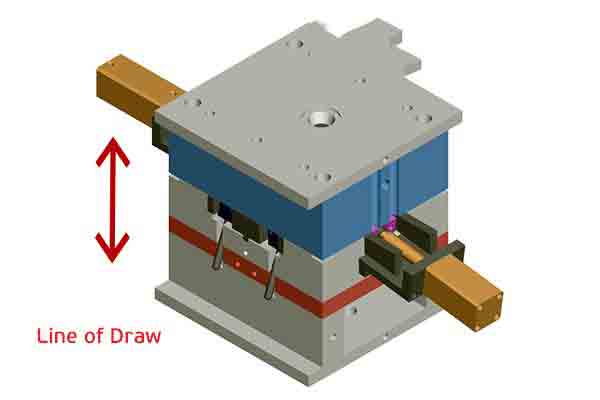
Closed tool showing line of draw
The direction of the tool opening not only affects the parting line but also the location and orientation of other components and features such as sliders and inserts, ejector pins and coolant lines.
On this complex shape, the parting line did not lie on a single plane but rather consisted of steps, angles and curves that followed the contours of several different features. We designed shutoff angles where these faces meet. These angles ensure good closure of the mold tool and help to prolong tool life.
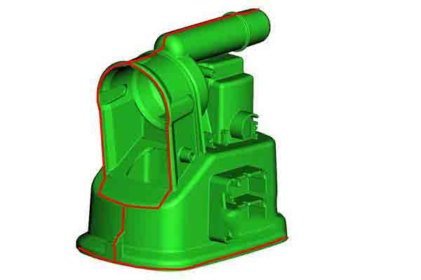
Detail of mold parting line
Designing the Mold Tool
Cooling Channels
After we optimized the 3D CAD design we prepared all the features of the tool required to mold it.
The first step was laying out the circuit for the cooling channels. It’s important to note that coolant is used not just to solidify the molten resin but to evenly distribute heat throughout the part. We designed a circuit that was balanced to control warpage while adapting to the contours of this profile. For this purpose, Moldflow and other analytic programs are a great benefit.
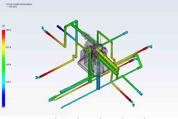
Thermal image of water coolant temperatures
Coolant circuits are built into both the core and cavity halves of the mold, and then connected to a pump and reservoir on the plastic injection molding machine where the flow rate and temperature are controlled.
Note that these channels have to be made perpendicular to the line of draw of the mold, and therefore at right angles to the ejector pin system.
Ejector Pins
Ejector pins push the part off the core after molding, but they leave a corresponding mark on the part surface. We had to be careful to place the pins in a balanced arrangement to ensure even distribution of force to avoid damaging the part or the pins themselves. We also needed to place pins strategically around the gate, where sufficient ejection pressure is needed to clear the gate in the event of a partial injection, or “short shot”.
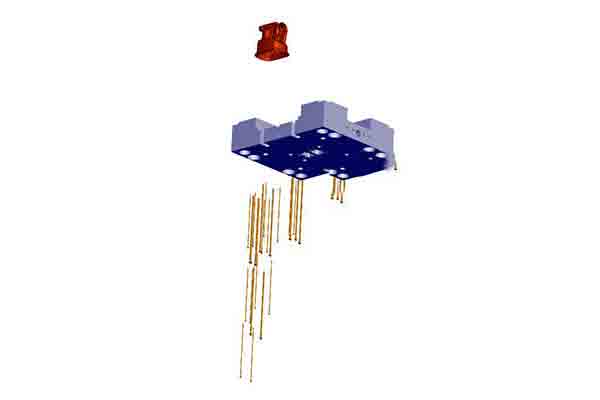
24 ejector pins are needed to release the part
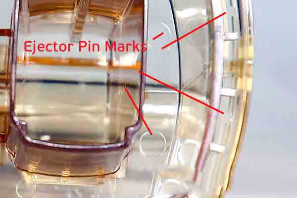
The customer wanted these marks to be raised from the surface, not indented.
Gate Location
What type of gate to use, and where to put it, are very important considerations for a successful injection molding tool design. Usually gates are placed as close as possible to the thickest sections of the part to ensure complete filling. In other cases however the gate location may need to be placed so that all features fill evenly and quickly within the limited cycle time.
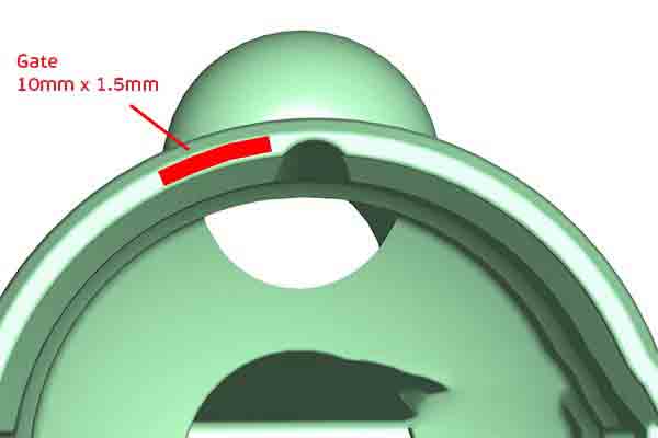
The edge gate was modified to increase flow
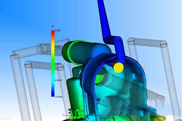
Detail of the gate and runner system
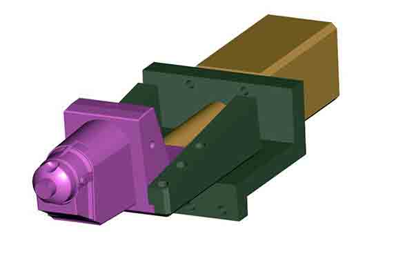
Sliders
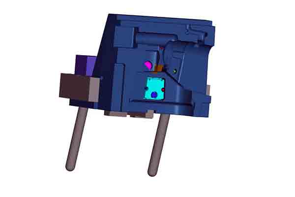
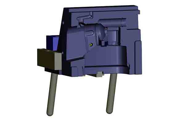
Sliders were used to form some of the features that could not be made in the line of draw. We had to design the system so it wouldn’t interfere with ejector pins, coolant circuits or the opening of the mold tool.
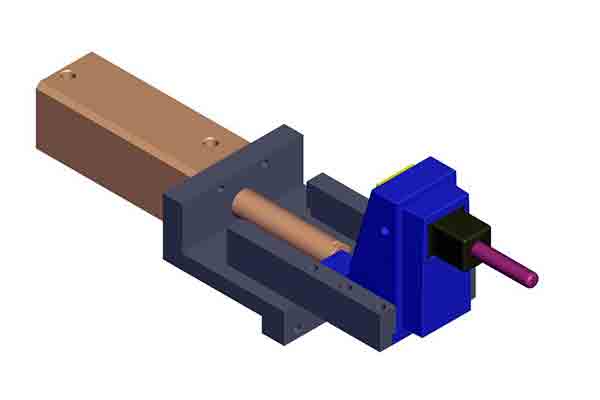
Final Mold Tool Design
The final mold assembly represented a careful orchestration of hundreds of separate components, all of it intersected with circuits for coolant as well as the gates and runners for molten plastic.
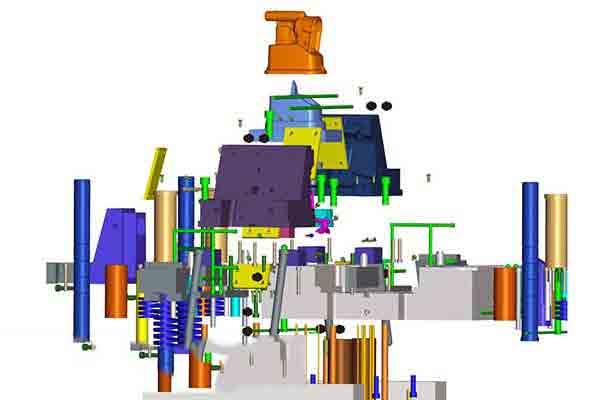
A complete assembly also requires many guides, springs, screws and plates to function properly
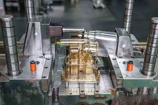
Completed mold tool showing sliding inserts
Was this helpful for you?
We hope that in this case study you were able to find useful information that can help you prepare your product designs for your next rapid prototyping or volume production order. We will apply the same careful Design for Manufacturing review when we help you bring your product ideas to life, so let’s get started today!

