Optimize Your Design for Manufacturing
Getting great results from plastic injection molding requires a respect for the properties of thermoforming plastic resins and how they behave inside of a mold tool. Using good design practices at the beginning of the product development cycle will help you to avoid common pitfalls and will improve the look and performance of your parts. Here are some suggestions for the most common causes of defects in plastic injected molded parts and how to avoid them for your next project.
Bosses
A boss is a stressed point of engagement, shaped like a post or pillar. It’s usually the place where a fastener like a screw will connect one piece to another.
Bosses can represent significant additional thermal mass in an injection molding so good design practices are needed to prevent sink marks and other defects.
- The boss should be radiused at the base, with a radius between 25-50% of the wall thickness;
- A boss should be attached to an adjacent external wall via a rib;
- Bosses can also be strengthened at the base with gussets for high-stress applications;
- The boss should be no taller than 3 times the outside diameter;
- A minimum draft angle on the outside should be 1/2°. A smaller draft is possible on the inside, if the tool and core have been well-polished;
- Two or more bosses should be located no closer than twice the adjacent wall thickness
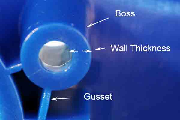
Follow good engineering practices when designing bosses.
Set bosses apart from walls to avoid sink marks
Draft Angle
This is a relief angle between the face of a part feature and the corresponding wall of the core/cavity, usually in parallel to the direction of the mold opening. We may recommend different angles dependent on the part’s geometry. A draft angle is needed to ensure that these features don’t scrape or seize against the tool wall as it is opened.
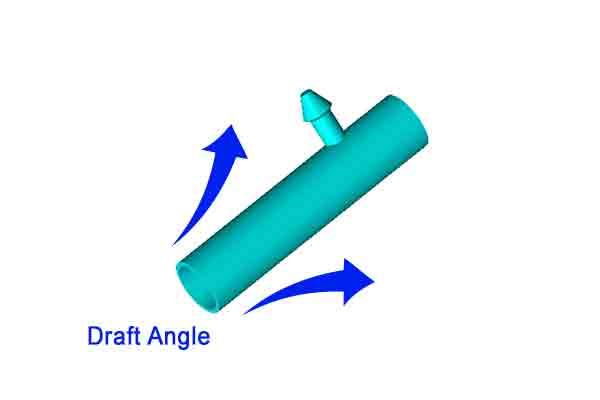
Draft angles are aligned with the direction that the mold opens, or the “draw” of the mold.
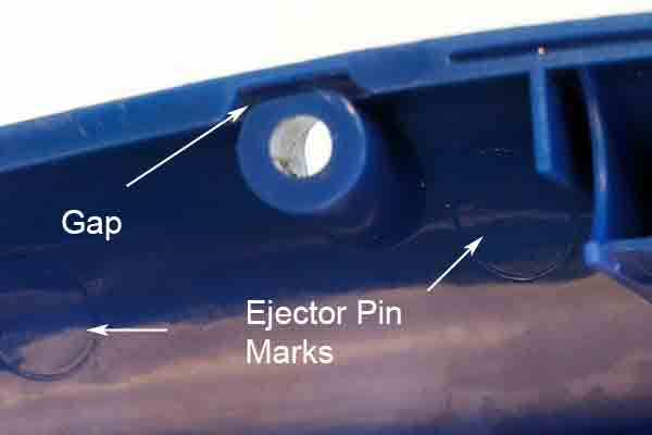
Ejector Pin Position
Ejector pins are simply metal rods placed at strategic locations inside a mold tool. When an injection cycle is done and the tool opens, the pins protrude from the mold cavity and help to push the now completed part free.
They are a necessary part of many mold tool designs but they will leave a corresponding shallow, circular mark on the part. Therefore, the pin location must be carefully chosen to avoid adversely affecting the fit and finish of the part.
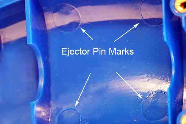
Ejector pin marks should be located on the B-side, or non-cosmetic surface of the part.
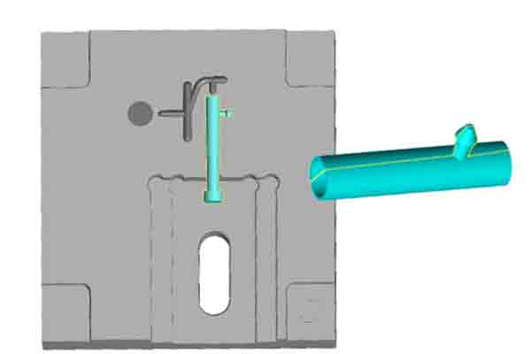
Gate Witness Marks
The gate is the nozzle from which liquid plastic is injected into a mold tool cavity. This area will leave a corresponding mark upon the finished part. It’s always best practice to therefore locate this mark in a place where it won’t affect the fit and finish, but this must be agreed upon before designing the mold tool.
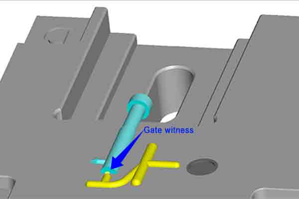
The gate witness is a small dimple of plastic left behind on the part after molding.
Parting Lines
This is the line where the two halves of a mold tool separate to release the part from a single large cavity. A mark will be left behind on the part which may be unavoidable. Care should be taken to hide this line if possible or work it into the overall part geometry or final design. This line can also be hidden via post-processing, such as with painting, sanding or bead blasting. Rough surface textures will tend to hide parting lines more than glossy ones.
Parting lines are hard to avoid but can be hidden within the overall design or by using heavy texture.
Ribs
Ribs act as supports to stiffen wall sections without adding much additional mass. They do have an effect on distribution of thermal stress so good design rules should be employed with their use.
- Where a rib meets a wall, the rib should be no thicker than 50% of the wall thickness;
- The base of the rib where it meets the wall should be radiused, between 25-50% of wall thickness;
- Rib height should be no more than three times wall thickness;
- Draft angles on ribs should be increased to allow for easier release than adjacent walls.
Gussets are similar to ribs but are smaller and are used for strengthening the base of a feature. The same design rules apply for gussets as for ribs.
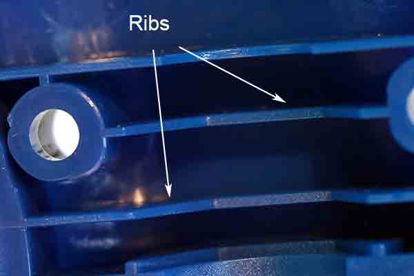
Ribs add strength while keeping weight down.
Sink Marks
Pits or depressions can be caused in the surface of a part because of the unequal rates of cooling between areas of greater and lesser thermal mass. Sink marks can be reduced to an acceptable level by following good design practice, as per the recommendations in our technical white paper.
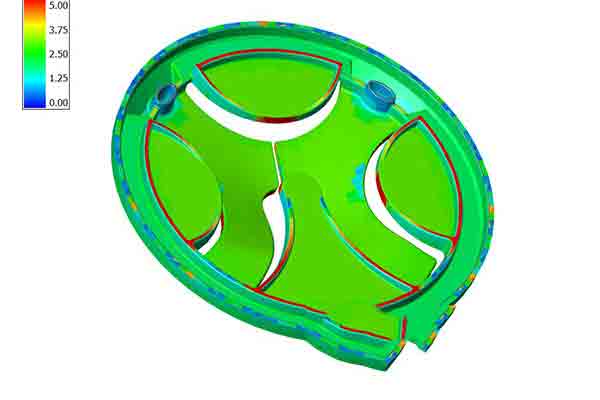
Heat mapping to identify thermal stress
Texture
Heavily textured or coarse surfaces on the interior walls of mold cavities may cause them to grip the surface of the plastic part firmly after it cools. This can cause scratching or binding when the part is ejected. The best way to avoid this problem is by designing in a larger than normal relief angle, dependent on the degree of texturing.
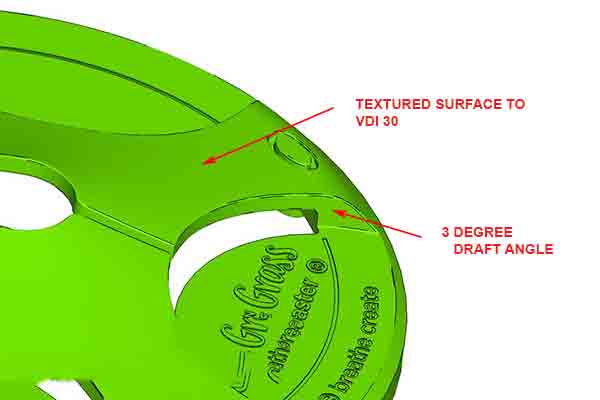
Textured surfaces need larger draft angles.
Wall Thickness
Designing uniform wall thickness is essential to controlling the distribution of heat within the part during molding.
To get the best results, follow these design tips for wall thickness. Be careful to note the type of plastic being molded, which may effect the rate of shrinkage in the mold.
- Adjacent walls should be equal in thickness wherever possible, but should in no case differ more than ~50%
- Long wall sections should be supported with ribs or gussets, instead of making them thicker for strength
- There should be a draft angle of 1 degree for every 2 cm in wall height
- Walls should have a slight radius at their base to relieve stress which can cause cracking or deformation
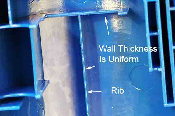
Even wall thicknesses cool at the same rate.
Weld Lines
A weld line is an area where two separate channels of flowing liquid plastic meet and solidify within a mold cavity. The opposing fronts will partially cool as they meet and they may trap gas, creating a characteristic mark on the finished part surface.
Weld lines may be unavoidable in many cases. They can be minimized to an acceptable degree by using conformal cooling channels where possible, by improving venting at the point of contact, or adjusting melt temperatures. Rough surface textures and/or painting will help to disguise weld lines.
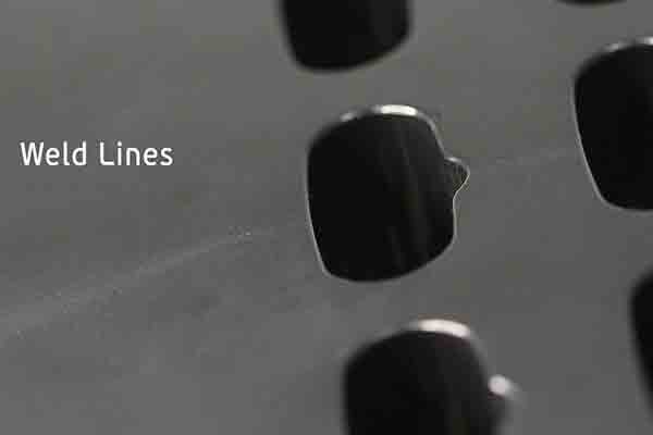
Weld lines are created where two fronts of thermal resin come together and cool at different rates.
Tolerance And Shrinkage
Plastic Injection Molding Service
Plastic injection molding is still the fastest and most economical way to make thousands or even millions of plastic parts for every conceivable application. To get the best results requires thoughtful application of sound design principles early in the product development stage. See our plastic injection molding page for more information about our service.